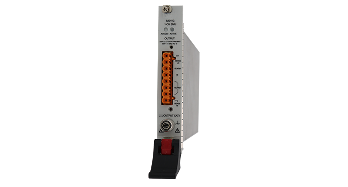
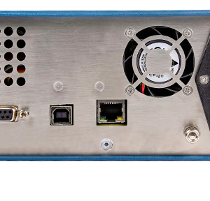
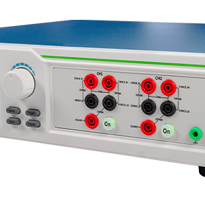
Single-Channel PXIe Precision Source Meter S2011C
The single channel PXIe source measure module is an economical and efficient unit, which supports most of the PXIe chassis manufacturers, supports multi card synchronization, and can be integrated into the production test system to improve the test efficiency of the system and reduce the cost;And support Adaptive PFC.
- Description
- Specifications
Description
Single-Channel PXIe Precision Source Meter S2011C
|
High transmission rate Single channel standard pxie precision power supply |
High range
±60 V、±3 A(direct)、±10A(pulse) |
High resolution
The minimum measurement resolution can reach 100fa / 100nv |
Easy to expand It is used in standard pxie chassis to easily realize multi-channel expansion |
Functions and advantage
|
(5) function in one body Voltage source |
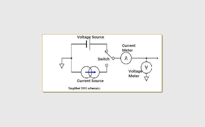 |
| 1、 Three quadrants as the source: the actual polarity of output V / I follows the source setting; 2、 The four quadrants are loads: CC and CV cooperate. When the load is used, the polarity of the load setting is opposite to the source polarity; |
 |
| Can test various equipment | 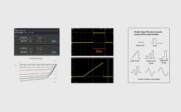 |
|
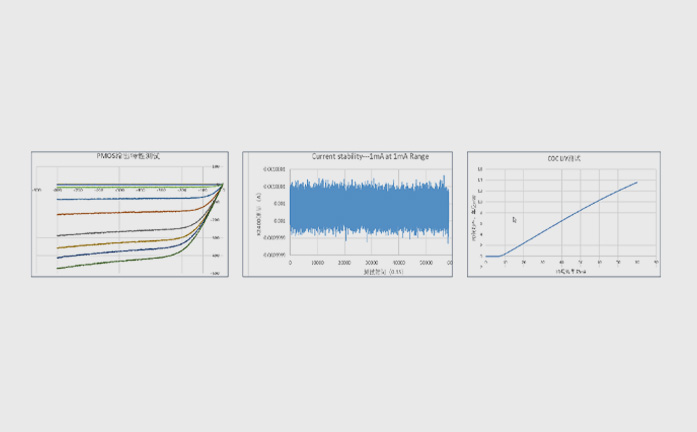
Capture more measurement data ♦ 6-and-a-half digital resolution: accuracy equivalent to 6-and-a-half digital multimeter; |
 |
| Rich scanning function | 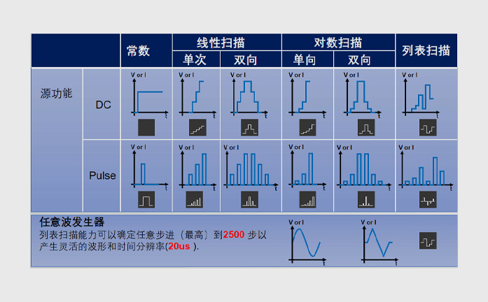 |
Voltage index
| Voltage accuracy | Range | Set resolution | Accuracy (1 year) ± (% reading + offset) | Typical noise (effective value)0.1 Hz-10Hz |
| ±60 V | 10 μV | 0.02%+3 mV | 200 μV | |
| ±6 V | 1 μV | 0.02%+0.3 mV | 60 μV | |
| ±0.6 V | 100 nV | 0.02%+100 μV | 20 μV | |
| Temperature coefficient | ±(0.15 × Accuracy)/°C (0℃-18℃,28℃-50℃) | |||
| Set time | <50uS (Typical value) | |||
| Overshoot | <±0.1% (Typical value, normal, step is 10% to 90% of the range, full scale point, resistive load test) | |||
| Noise 10Hz-20MHz | 6V voltage source, 3A resistance load,<3mV RMS | |||
Current index
| Current accuracy | Range | Set resolution | Accuracy (1 year) ± (% reading + offset) | Typical noise (effective value)0.1 Hz-10Hz |
| ±10 A1 | 1 μA | 0.03% + 2mA | 20 μA | |
| ±3 A | ||||
| ±1 A | 100 nA | 0.03% + 90 μA | 3 μA | |
| ±100 mA | 10 nA | 0.03% + 9 μA | 200 nA | |
| ±10 mA | 1 nA | 0.03% + 900 nA | 20 nA | |
| ±1 mA | 100 pA | 0.03% + 90 nA | 2 nA | |
| ±100 μA | 10 pA | 0.03% + 9 nA | 200 pA | |
| ±10 μA | 1 pA | 0.03% +1 nA | 30 pA | |
| ±1 μA | 100 fA | 0.03% + 200 pA | 5 pA | |
| Temperature coefficient | ±(0.15 × Accuracy)/°C (0℃-18℃,28℃-50℃) | |||
| Set time | <100us (Typical value) | |||
| Overshoot | <±0.1% (Typical value, normal, step is 10% to 90% of the range, full scale point, resistive load test) | |||
1,10A range only supports pulse mode, and the accuracy is typical
Pulse source index (4 lines)
| Minimum programmable pulse width | 100μs |
| Pulse width programming resolution | 1μs |
| Pulse width programming accuracy | ±10μs |
| Pulse width jitter | 2μs |
| Pulse width definition | As shown in the following figure, the time from 10% leading edge to 90% trailing edge |

| Pulse technical index | Maximum current limit | Maximum pulse width | Maximum duty cycle |
| 1 | 0.4A/50V | DC,unlimited | 100% |
| 2 | 1A/20V | DC,unlimited | 100% |
| 3 | 3A/6.6V | DC,unlimited | 100% |
| 4 | 10A/20V | 1mS | 5% |
| 5 | 10A/50V | 400uS | 2% |
Rise time of pulse source (4 lines)
| Output | Maximum output | Typical rise time 1 | Typical stabilization time 2 | Test load |
| Voltage source | 50 V | 250μS | 400μS | No load |
| 5 V | 40 μS | 100 μS | No load | |
| Current source | 10A~100 μA | 90 μS | 250 μS | With full load 3 |
| 10 μA | 120 μS | 300 μS | With full load 3 | |
| 1 μA | 300 μS | 600 μS | With full load 3 |
1,The time required for the pulse front from 10% to 90%.
2,The time required for the pulse to reach 1% of the final value.
3,Test condition: normal pure resistance full load voltage rises to 6V
DC I-V output capacity

Pulse I-V output capability

Output setup time
| Output | Range | Typical output setup time 1 | Test conditions: | ||
| Fast2,3 | Normal2 | Slow2 | |||
| Voltage source | 60V | <120μS | <300μS | <1ms | The time required to reach within 0.1% of the final value under open circuit load. In steps ranging from 10% to 90%. |
| 6V | <30μS | <50μS | <300us | ||
| 0.6V | <30μS | <50μS | <300us | ||
| Current source | 3A~100ua | <50μS | <100μS | <0.8ms | Under normal full load condition, the voltage output reaches 6V. The time required to reach within 0.1% of the final value (0.3% for the 3 a range). Steps are 10% to 90% of the range |
| 10μA | <100μS | <150μS | <0.8ms | ||
| 1uA | <300μS | <400uS | <1ms | ||
1,The user can adjust the PID parameters according to the load characteristics to obtain the appropriate setup time or stability.
2,Output conversion rate:Fast,Normal,Slow。
3,The output of fast mode may have large overshoot under different ranges or load conditions. It is recommended to use normal or slow mode for overshoot sensitive equipment. Users can choose
Sampling rate and NPLC settings
| Collocation method | Configuration scope |
| NPLC | 0.00005PLC ~ 10PLC |
| Sampling Rate | 5sps ~ 1Msps |
Derating of measurement accuracy(PLC<1)
Error: percentage of range increase
| PLC | Range | ||||||
| 600mV | 6V | 60V | 1uA | 10uA | 100uA to 100mA | 1A to 3A | |
| 0.1 | 0.02% | 0.01% | 0.01% | 0.02% | 0.01% | 0.01% | 0.01% |
| 0.01 | 0.30% | 0.03% | 0.02% | 0.20% | 0.04% | 0.02% | 0.02% |
| 0.001 | 3.20% | 0.40% | 0.10% | 2.50% | 0.40% | 0.03% | 0.03% |
Supplementary features
| Sensing mode | 2-wire or 4-wire (remote sensing) connection |
| Maximum sensing lead resistance | 1 kΩ(accuracy rating) |
| Maximum voltage between remote sensing output terminal and sensing terminal | 1V |
| Maximum output voltage of output connector | >Full scale 105%(60V range>60.5V) |
| SWEEP scanning | The scanning interval is configurable from 20us to 16S, and the maximum scanning time is 8K points |
| Auto Range | Support. It is recommended to switch off the output before switching the range for overshoot sensitive equipment |
| Delay measurement(SOURCE DELAY) | Support. It is recommended that the user set the appropriate source delay to obtain more accurate measurement |
| Over temperature protection | When the internal temperature is detected to be too high, the output will be turned off, and the operation will be resumed when the temperature returns below 65 ℃ |
| Other output abnormal protection | Power off and restart to recover operation or hardware damage |
Environmental indicators
| Environment | Use in indoor facilities |
| Work | 0 ° C to + 50 ° C, 30% to 70% relative humidity non condensing |
| Store | -30 ° C to 70 ° C, 10% to 90% relative humidity non condensing |
| Altitude | Working height: 0 m to 2000 m, storage: 0 m to 4600 M |
| Preheat | 1 hour |


