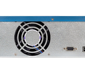
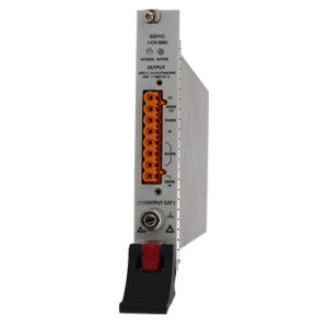
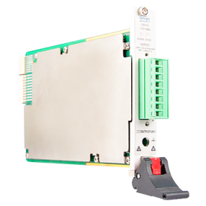
Single-Channel Precision Source Meter S3012H
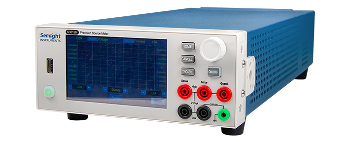
The cost-effective single-channel high-precision source meter, standard half-rack width, and rich LCD screen operation interface make it an ideal choice for various high-precision and high-resolution testing tasks.
- Description
- Additional information
- Specifications
Description
Single-Channel Precision Source Meter S3012H
|
High range Range: ±200 V, ±3 A (DC), ±10A (pulse) |
High resolution
Minimum measurement resolution up to 100fA/100nV |
High sample rate
Up to 1M ADC sampling rate can be supported) |
hardware synchronization
Single-machine multi-machine synchronization, pure hardware high-speed synchronization, can realize multi-channel low-latency synchronization |
Functions and advantage
|
5 functions in one Power source |
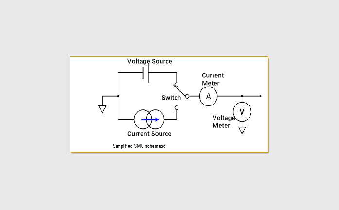 |
| 1. The first and third quadrants are the source: the actual polarity of the output V/I follows the source setting;
2. The second and fourth quadrants are the load: CC and CV cooperate, when the load is used, the load setting polarity is opposite to the source polarity; |
 |
| Various devices can be tested | 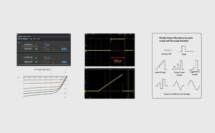 |
|
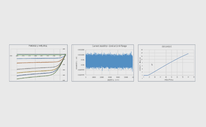
Capture more measurement data ♦ 6½-digit digital resolution: The accuracy is equivalent to a 6½-digit digital multimeter; |
 |
| Rich scanning functions | 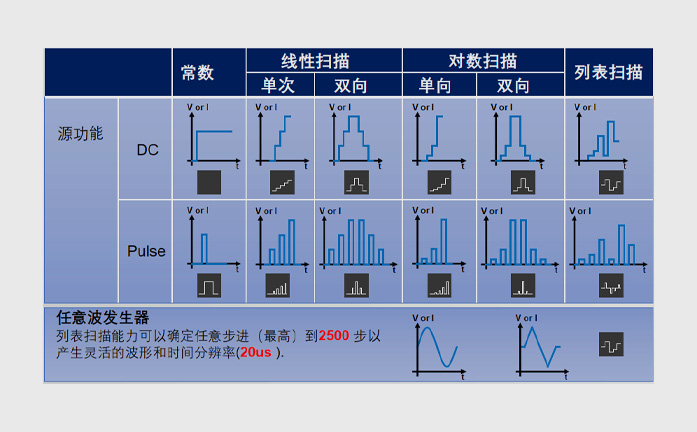 |
Additional information
| Weight | 5.2 kg |
|---|---|
| Dimensions | 45.0 × 21.2 × 10.5 cm |
Voltage source indicator
| Voltage setting accuracy | Range | Set resolution | Accuracy (1 year) ±(% reading + offset) | Typical Noise (RMS))0.1 Hz-10Hz |
| ±200 V | 1mV | 0.02%+40 mV | 600 μV | |
| ±20 V | 100 μV | 0.02%+5 mV | 100 μV | |
| ±6 V | 10 μV | 0.02%+500 μV | 4 μV | |
| ±200 mV | 1 uV | 0.02%+200 μV | 2 μV | |
| Temperature Coefficient | ±(0.15 × Accuracy)/°C (0℃-18℃,28℃-50℃) | |||
| Ssingle channel maximum output power | 30W: ±20V@1.5A;30W: ±200 V@0.15A;18W: ±6 V@3A | |||
| Set time | <800uS (Typical) | |||
| 过冲 | <±0.1% (Typical, Normal, steps are 10% to 90% of range, full scale point, resistive load test) | |||
| Noise 10Hz-20MHz | 6V voltage source, 3A resistive load,<3mV RMS | |||
Current source indicator
| Current setting accuracy | Range | Set resolution | Accuracy (1 year) ±(% of reading + offset) | Typical Noise (RMS))0.1 Hz-10Hz |
| ±10 A1 | 50 μA | 0.4% + 40 mA | NA | |
| ±3 A | 20 μA | 0.05% + 5 mA | 10 μA | |
| ±1.5A | 5 μA | 0.02% + 500 μA | 3 μA | |
| ±150 mA | 500 nA | 0.02% + 25 μA | 800 nA | |
| ±15 mA | 50 nA | 0.02% + 2.5 μA | 100 nA | |
| ±1.5 mA | 5 nA | 0.02% + 150 nA | 20 nA | |
| ±150 μA | 500 pA | 0.02% + 25 nA | 200 pA | |
| ±15 μA | 50 pA | 0.02% + 3 nA | 75 pA | |
| ±1.5 μA | 5 pA | 0.03% + 600 pA | 50 pA | |
| ±150 nA | 500 fA | 0.05% + 300 pA | 10 pA | |
| Temperature Coefficient | ±(0.15 × Accuracy Index)/°C (0℃-18℃,28℃-50℃) | |||
| Single channel maximum output power | 30W: ±20V@1.5A;30W: ±200 V@0.15A;18W: ±6 V@3A | |||
| Set time | <500us(Typical) | |||
| Overshoot | <±0.1% (Typical, Normal, steps are 10% to 90% of range, full scale point, resistive load test) | |||
1, 10A The range only supports pulse mode, and the accuracy is typical
Voltmeter indicator
| Voltage measurement accuracy | Range | Display resolution | Accuracy (1 year) ±(% of reading + offset) |
| ±200 V | 100 μV | 0.02% + 40 mV | |
| ±20 V | 10 uV | 0.02% + 5 mV | |
| ±6 V | 1 uV | 0.02% + 500 uV | |
| ±200mV | 100 nV | 0.02% + 200 μV | |
| Temperature Coefficient | ±(0.15 × Accuracy)/°C (0℃-18℃,28℃-50℃) | ||
Ammeter indicator
| Current measurement accuracy | Range | Display resolution | Accuracy (1 year) ±(% of reading + offset) |
| ±10 A1 | 10 μA | 0.4% + 25 mA | |
| ±3 A | 10 μA | 0.05% + 5 mA | |
| ±1.5A | 1 μA | 0.02% + 500 μA | |
| ±150 mA | 100 nA | 0.02% + 25 μA | |
| ±15 mA | 10 nA | 0.02% +2 μA | |
| ±1.5 mA | 1 nA | 0.02% + 150 nA | |
| ±150 μA | 100 pA | 0.02% + 20 nA | |
| ±15 μA | 10 pA | 0.02% +3 nA | |
| ±1.5 μA2 | 1 pA | 0.03% + 600 pA | |
| ±150 nA2 | 100fA | 0.05% + 300 pA | |
| Temperature Coefficient | ±(0.15 × Accuracy)/°C (0℃-18℃,28℃-50℃) | ||
1, The 10A range only supports pulse mode, and the accuracy is typical
2, For small current measurement, it is recommended to use a triaxial cable to connect Force Hi is connected to the core wire, Guard is connected to the inner shield layer, the outer shield layer is connected to the protective ground, Force Lo is connected to the core wire, the inner shield layer is not connected, and the outer screen is not connected.
The shielding layer is connected to the protective ground, and the rated insulation voltage of the coaxial cable is not less than 250V.
Resistance Meter Specifications (4-wire)
| Resistance measurement accuracy | Range | Display resolution | Default measurement current | Typical accuracy (1 year) ±(% of reading + offset) |
| 1 Ω | 1 uΩ | 1 A | 0.09% + 0.5 mΩ | |
| 10 Ω | 10 uΩ | 100 mA | 0.065% + 5 mΩ | |
| 100 Ω | 100 uΩ | 10 mA | 0.065% + 50 mΩ | |
| 1 KΩ | 1 mΩ | 1 mA | 0.055% + 500 mΩ | |
| 10 KΩ | 10 mΩ | 100 uA | 0.065% + 5 Ω | |
| 100 KΩ | 100 mΩ | 10 uA | 0.07% + 50 Ω | |
| 1 MΩ | 1 Ω | 1 uA | 0.05% + 500 Ω | |
| 10 MΩ | 10 Ω | 0.1 uA | 0.65% + 5KΩ | |
| 100 MΩ | 100 Ω | 0.05 uA | 1.27% + 10 KΩ | |
| Temperature Coefficient | ±(0.15 × Accuracy)/°C (0℃-18℃,28℃-50℃) | |||
| Manual current source resistance measurement (4-wire) | Total Error = Measured Voltage/Current Source Set Current = Resistance Reading x (Gain Error Percentage of Voltage Source Range + Gain Error Percentage of Ammeter Range + Current Source Range Offset Error/Set Current) + (Voltage Source Range Offset Error /set current value) Example: Current source setting current=1A Voltage measurement range=6V overall error=(0.02%+0.02%+500uA/1A)+(500uV/1A) =0.09%+0.5mΩ |
|||
Pulse source indicator (4 lines))
| Minimum programmable pulse width | 100μs |
| Pulse width programming resolution | 1μs |
| Pulse width programming accuracy | ±10μs |
| Pulse width jitter | 2μs |
| Pulse width definition | Time from 10 % leading edge to 90 % trailing edge as shown below |

| Pulse Specifications | Maximum current limit | Maximum pulse width | maximum duty cycle |
| 1 | 0.15A/200V | DC,unlimited | 100% |
| 2 | 1.5A/20V | DC,unlimited | 100% |
| 3 | 3A/6V | DC,unlimited | 100% |
| 4 | 3A/20V | 1mS | 10% |
| 5 | 10A/6V | 1mS | 10% |
Pulse source rise time (4-wire)
| Output | Range | Typical rise time 1,3 | Typical settling time 2,3 | Test load |
| Power source | 200 V | 600 μS | 1.5 mS | No load |
| 20 V | 200 μS | 360 μS | No load | |
| 6 V | 160 μS | 300 μS | No load | |
| Current source | 10 A | 140 μS | 320 μS | Fully loaded |
| 3 A | 120 μS | 280 μS | Fully loaded | |
| 1.5 A | 120 μS | 280 μS | Fully loaded | |
| 150 mA | 120 μS | 280 μS | Fully loaded | |
| 15 mA | 120 μS | 280 μS | Fully loaded | |
| 1.5 mA | 120 μS | 280 μS | Fully loaded |
1, The time it takes for the leading edge of the pulse to go from 10% to 90%.
2, The time it takes for a pulse to reach 1% of its final value.
3, The current source test is based on the test under the 6V voltage range, with a 105% full-scale clamp setting.
I-V output capability

Output settling time
| Output | Range | Typical output settling time | Test Conditions | ||
| Fast 1,2 | Normal1 | Slow1 | |||
| Power source | 200V | <1.3mS | <1.5mS | <2.5ms | Time required to reach within 0.1% of final value under open load conditions. The step is the range 10% to 90%. |
| 20V | <300μS | <360μS | <1ms | ||
| 6V | <150μS | <250μS | <1ms | ||
| 200mV | <200μS | <250μS | <1ms | ||
| Current source | 3A | <200μS | <280μS | <1.2ms | Time required to come within 0.1% (0.3 % for 3 A range) of final value under short circuit conditions. Steps are 10% to 90% of the range. 6V voltage range, 105% full-scale clamp setting |
| 1.5A | <200μS | <280μS | <1.2ms | ||
| 150mA | <200μS | <280μS | <1.2ms | ||
| 15mA | <200μS | <280μS | <1.2ms | ||
| 1.5mA | <200μS | <280μS | <1.2ms | ||
| 150μA | <250uS | <300uS | <1.2ms | ||
| 15μA | <250uS | <1.2mS | <2ms | ||
| 1.5uA | <600uS | <1.2mS | <5mS | ||
| 150nA | <600uS | <5mS | <12mS | ||
1, output slew rate:Fast,Normal,Slow。
2, In the Fast mode, the output may have a large overshoot under different ranges or load conditions. It is recommended to use the Slow mode for overshoot-sensitive devices.
Sample rate and NPLC settings
| Configuration method | Configuration scope |
| NPLC | 0.00005PLC ~ 10PLC |
| Sampling Rate | 5sps ~ 1Msps |
Measurement accuracy derating(PLC<1)
Error Increase Percentage of Range
| PLC | Range | ||||||
| 200mV | 6V | 20 to 200V | 150nA to 1.5uA | 15uA | 150uA to 150mA | 1.5A to 3A | |
| 0.1 | 0.02% | 0.01% | 0.01% | 0.02% | 0.01% | 0.01% | 0.01 |
| 0.01 | 0.30% | 0.03% | 0.02% | 0.20% | 0.04% | 0.02% | 0.02% |
| 0.001 | 3.20% | 0.40% | 0.10% | 2.50% | 0.40% | 0.03% | 0.03% |
Supplementary Features
| Sensing mode | 2-wire or 4-wire (remote sensing) connection |
| Maximum sense lead resistance | 1 kΩ(rated accuracy) |
| 2 Line voltage drop inside line | <60mV/A |
| The maximum voltage between the remote sensing output terminal and the sensing terminal | 2V |
| Output connector maximum output voltage | >DC floating voltage 105%(200V range>202V) |
| DC floating voltage | ±250 V DC |
| SWEEP scanning | Configurable scan interval from 20uS to 16S, maximum 64K points per scan |
| Autoranging | Support, overshoot sensitive equipment is recommended to turn off the output before switching the range and then perform the range switching action |
| Delay measurement(SOURCE DELAY) | Supported, it is recommended that the user set the appropriate SOURCE DELAY to obtain a more accurate measurement value |
| Over temperature protection | When it is detected that the internal temperature is too high, the output will be turned off, and the operation will resume when the temperature returns to below 65 degrees. |
| Overvoltage protection(OVP) | When the output exceeds the OVP set value, the output is turned off, and the device can be further operated after reset. Accuracy:±(1%Setting+500mV) |
| Other output abnormal protection | Power off and restart, recoverable operation or hardware damage |
Communication port
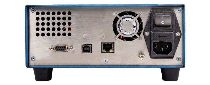
| Ethernet | 100BASE-T / 10BASE-T | |
| USB | USB 2.0 HOST(forward) | |
| USB 2.0 DEVICE(back) | ||
| Number I/O DB9 | Pin5 | Land |
| Absolute Maximum Input Voltage: 5.25 | Pin6 | IO1, digital I/O, sync signal input port |
| Absolute minimum input voltage: -0.25V | Pin7 | IO2, digital I/O, sync signal output |
| Minimum logic high level:2.1V | ||
| Highest logic low level:0.7V, | ||
| Maximum logic output current:2mA | ||
| Maximum current sink:-50mA | ||
Environmental indicators
| Surroundings | Use in indoor facilities |
| Work | 0 °C to +50 °C, 30 % to 70 % relative humidity non-condensing |
| Store | -30 °C to 70 °C, 10 % to 90 % relative humidity non-condensing |
| Altitude | Altitude work: 0 m to 2000 m, storage: 0 m to 4600 m |
| Power supply | 90 V to 264 V, 47 Hz to 63 Hz, 250 VA max |
| Warm up | 1 Hour |
| Size | 450 × 212× 105mm(including foot pads, handles and knobs) |
| Weight | Net weight 5.2 kg |
Front panel
| Show | 5.0 inch TFT LCD screen, capacitive touch mode, resolution 800*480 |
| Fixed function keys | Trigger,Home,Cancel,Power button, channel switch, rotary button |
| Non-fixed function keys | LCD mapping function keys |
| Interface | USB host interface, output interface, chassis ground interface |
Rear panel
Power cord, USB cable, test leads (two), quick reference, USB stick (includes PDF manual, quick I/V measurement software and drivers).
| Product number | |
| S3012H | Single-Channel Precision Source/Measure Unit, Pulse Source |


