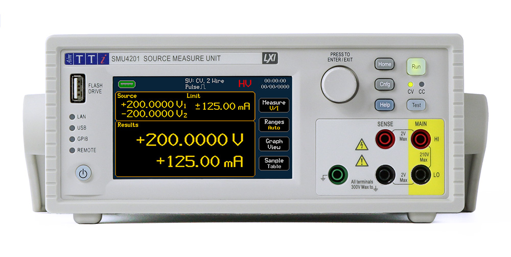
SMU4000 Series Source Measure Unit with 20 and 200V versions
- 4-quadrant Source, Sink & Measure
- 0.015% basic accuracy with 6½ digit resolution.
- Sense terminals for 4 wire operation and guard capabilities
- PowerFlex technology: up to ±210V, up to ±3.15A (SMU4201) or up to ±21V, up to ±3.15A (SMU4001), 25W power envelope.
- 0.1µV & 100fA resolution
- Fast measurement speeds up to 200µs (5k/s)
- Continuous or pulsed high speed outputs with Linear/Log or arbitrary list sweeps
- Compact size
- Internal memory, up to 100k measurements, up to 100k steps
- ‘SMU Link’ allows two SMUs to be linked together for synchronous operation (optional accessory)
- Full control of multiple units with Test Bridge SMU Windows software (free download)
 AIM-SMU4000_Series_Data_Sheet_issue_1.pdf
 SMU4000_Safety_Documentation+Quick_Start_Guide_issue_1.pdf
- Description
- Additional information
- Data and Downloads
Description
SMU4000 Series Source Measure Units
| The SMU4000 Series from Aim-TTi combines a high speed four-quadrant power source/sink and sensitive precision measurement capabilities in one unit under software control for rapidly characterizing or verifying non-linear circuits or components.
It is based around high-speed, high-precision measurement of voltage and current which is used in a digital feedback loop to precisely regulate the source/load voltage and current. This allows the instrument to rapidly and accurately apply a stimulus or provide a precision load and accurately measure the result. Designed from the ground up to be flexible enough for a research lab and fast and affordable enough for use on a high volume production line, the SMU4000 series represents a competitive new entry into the world of Source Measure Units. This product tour consists of a series of web pages. Use the blue navigation buttons at the top or bottom of the page to step through it. You can also use the select list at the top of the page or the map (icon top right) to select a particular topic. More information is available by clicking on the info button at the top right. |
 |
Why use a Source Measure Unit?

An SMU is effectively multiple instruments in one, but being designed with tight integration and control brings many added benefits over using the traditional separate power supply, load, DMM and arbitrary function generator. |
StabilityAn SMU has the ability to keep the output stable during unexpected load changes by precisely measuring its own voltage and current and feeding this back to the source SpeedInterconnection of all the individual elements in a single unit increases the timing accuracy and speed of communications between the source and measurement circuitry Not having to rely on external communication lines to keep multiple instruments in sync cuts down control overhead times. Built in sweep and sequencing capabilities keep external control signals to a minimum. AccuracyMeasurement error is considerably reduced when compared to individual instruments in one setup. Close integration of the source and measurement elements achieves a far more reliable performance with better settling times and far superior synchronization. ConvenienceNot having to connect up and configure multiple instruments, but simply recall a preset brings considerable time savings. The single compact bench case saves space and reduces clutter. Two SMU4000 can fit in 2U rack space and be synced together with the SMU-Link (optional). You can go from sourcing to sinking power without swapping from a power supply to a load, run sweeps with automated data collection without writing automation code and use built in protection features that are hard to implement with separate instruments. |
Source Measure units – multiple instruments in one
 An SMU combines the functionality of a power source with positive and negative constant voltage or constant current capabilities, an electronic load, a precision ammeter and a precision voltmeter. This is tied together with a high speed sweep / pulse generator and data collection engine with graphing capabilities. Because it is purpose built for rapid characterization, it is far more than the sum of its parts. Special care has been taken over stability and protection, settling times, and the speed and accuracy of its measurements. Low noise techniques have been used to facilitate the measurement of very small currents or voltages. The touchscreen menu system prioritizes ease of use, making presets available for common usage scenarios. Two SMU4000 series can be joined together with the SMU-LINK (optional accessory) which enables them to be synchronized, effectively creating a 2 channel SMU that fits in a 2U rack space (rack kit optional).
SMU4000 Series Feature Overview
 |
|
SMU4000 Series Versions
SMU4001The SMU4001 can provide up to ±21V or up to ±3.15A within a 25W power limit |
SMU4201The SMU4201 can provide up to ±210V or up to ±3.15A within a 25W power limit |
SMU4000 Series compact form factor
 |
Bench-top OperationThe SMU4000 series use a minimum of bench space. Protective surrounds guard against knock damage and a multi-position stand angles the instrument conveniently as well as providing a carry handle.* The footprint of the SMU4000 case is about the same as a sheet of A4 paper (214mm wide by 269mm deep). It is 2U/86.5mm high, half rack width and weighs under 4.5kg. Rack MountingFor system applications the SMU4000 Series can be rack mounted. With the protective surrounds and handle removed the size is half rack width by 2U high. One or two units can fit in the optional RM200A 2U rack kit (which includes a half width blanking panel). *Note: the images of the side of the case show a TG Series Function generator which uses the same case but has different front panel connections and encoder. |
 |
SMU4000 PowerFlex
 |
The Aim-TTi PowerFlex system provides a semi constant power characteristic so that the current capability rises as the voltage falls.
The SMU4000 series achieves full instrument power across the majority of the voltage range, unlike conventional SMUs where the maximum power can only be achieved at the top of each voltage range. Both the SMU4001 and the SMU4201 can source up to 3A at 8V or 1.25A at 20V (top diagram) with a range of other maximum voltage and current combinations between the two. The SMU4201 has a further high voltage capability which can source 0.5A at 50V and up to 0.125A at 200V within the same 25W power envelope (lower diagram). |
SMU4000 Easy Setup presets
The SMU4000 series provides eight ‘Easy Setup’ presets to allow instant use of the SMU for specific use cases:
These primarily configure the mode of operation of the source/sink. In all cases the measured voltage, current and derived measurements are available. These setups can be edited using the manual setup mode configuration so also act as starting points for more complex configurations. |
*Operation Modes: SV: Source Voltage, SC: Source Current, LC: Load Current, LR: Load Resistance, LP: Load Power, MV: Measure Voltage, MC: Measure Current, MR: Measure Resistance- Voltage Limited, MHR: Measure Resistance- Current Limited |
||||||||||||||||||||||||||||||||||||||||||||||||||||
SMU4000 Setups and Sequencing
 |
SetupsA setup is an instrument configuration that can be saved to file and recalled. Each can put the instrument into one of the following instrument operating modes which determine primarily how the source/sink is controlled – in all modes voltage and current and derived values are measured:
These can be further configured with terminal selection, measurement count, source shape (steady, pulse, sweep etc.), output off state, source level, limits and protection, timing options, result sorting (pass/fail) and mathematical operations on the results. Not all configuration options are applicable to all operation modes. The resulting setup can then be stored and recalled for future use and run with the “Run” button or trigger. SequencingSetups as described above can be chained into sequences with additional logic at each step (see diagram). These become particularly powerful when combined with digital IO and event conditions based on the measurements. A sequence then becomes another “mode” and is run with the “Run” button or from external trigger. Sequences can be saved and recalled. |
SMU4000 measurement precision
 |
6½ digit, 0.01µV & 100fA resolutionThe SMU4001 has four voltage ranges from 20mV with 10nV resolution to 20V with 10µV resolution. The SMU4201 adds a 200V range with 100µV resolution. Voltage measurement burden is >10GΩ ±80pA. Both units have nine current ranges from 200nA with 100fA resolution to 3A with 1µA resolution. Basic accuracy is ±0.015% – see the specifications in the datasheet for details. 4 wire remote senseIn order to remove the effects of the resistance of the connection leads from low impedance measurements, sense terminals are provided, allowing precise regulation and measurement at the device under test and not just at the SMU terminals. Driven Guard TerminalsWhen measuring from the rear terminals, a pair of guard outputs are available which provide a buffered output at the same potential as the force Hi terminal. This is for connection to shields which add protection from DC leakage currents in the sense circuits by surrounding them with a voltage identical that of the measurement node and are essential for making accurate measurements of small currents in high impedance applications. |
High Reactance ModeWhen attempting to source into reactive loads (capacitive and/or inductive), engaging the SMU4000 High Reactance Mode uses a lower bandwidth feedback loop with reduced compensation speed and increased settling time to provide more robust performance, reducing the chances of overshoot, ringing or instability. Low noiseTo accurately measure DC values in the presence of noise, the SMU4000 series measures at very high speeds internally and averages the results over user settable time periods. To minimize the effects of mains frequency interference, the averaging can be set to use integer multiples of the Power Line Cycle period (PLC). In this mode, the instrument internally measures the actual power line frequency and automatically synchronizes its averaging period. |
SMU4000 measurement speed
 |
Built for Speed
Auto DelayThe SMU4000 can implement an automated measurement delay to wait only as long as is necessary for the measurement to settle before recording a measurement. In most applications this will be the fastest way to measure. Measurement PeriodThe measurement period defines the amount of time that each measurement is averaged for and is a trade-off between measurement accuracy and measurement speed. In the absence of noise, an accurate measurement of a stable system can be made in as little as 200µs. TriggeringMeasurements that depend on external processes can be triggered by remote commands or the Digital IO port and can report pass/fail results back extremely fast for fully automated tests. |
SMU4000 measurement statistics
 |
The measurement statistics screen provides information based on the primary and secondary measurement data from the sample table.
This is updated live as new data is recorded and is available at any time. |
SMU4000 graphing
 |
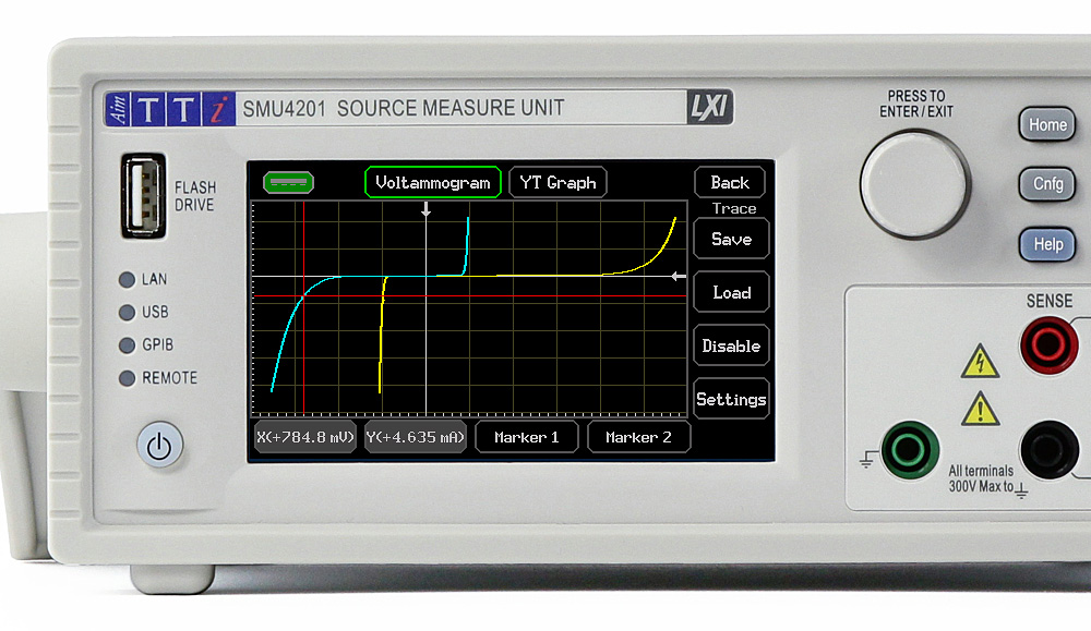
The SMU4000 Series provides graphical display of the measured results on screen without requiring external software. This may be real time data or data already in the buffer. Traces may be saved and recalled. Graphs may be Auto-Scaled (the graticule is auto-ranged to fit the data with the most appropriate number of units per division) or Auto-Fit (the graph is scaled to show all the data at once without maintaining a defined range of units per division) or it may be manually scaled.
Two main types of graph are provided:
A pair of markers are available to measure on either or both axes. The screen can be exported to USB. |
SMU4000 Sweep Engine
 |
The SMU4000 can source or sink different levels over time in a variety of “shapes” which can be run on demand, repeated or sequenced in order to generate multi-dimensional data sets:
For each mode there are a range of options for additional parameters. For example, sweep mode can sweep up and down in a dual sweep mode. The measurement units that are swept depend on the operation mode, for example they are Watts in the LP (Load Power) operation mode. |
SMU-LINK
 |
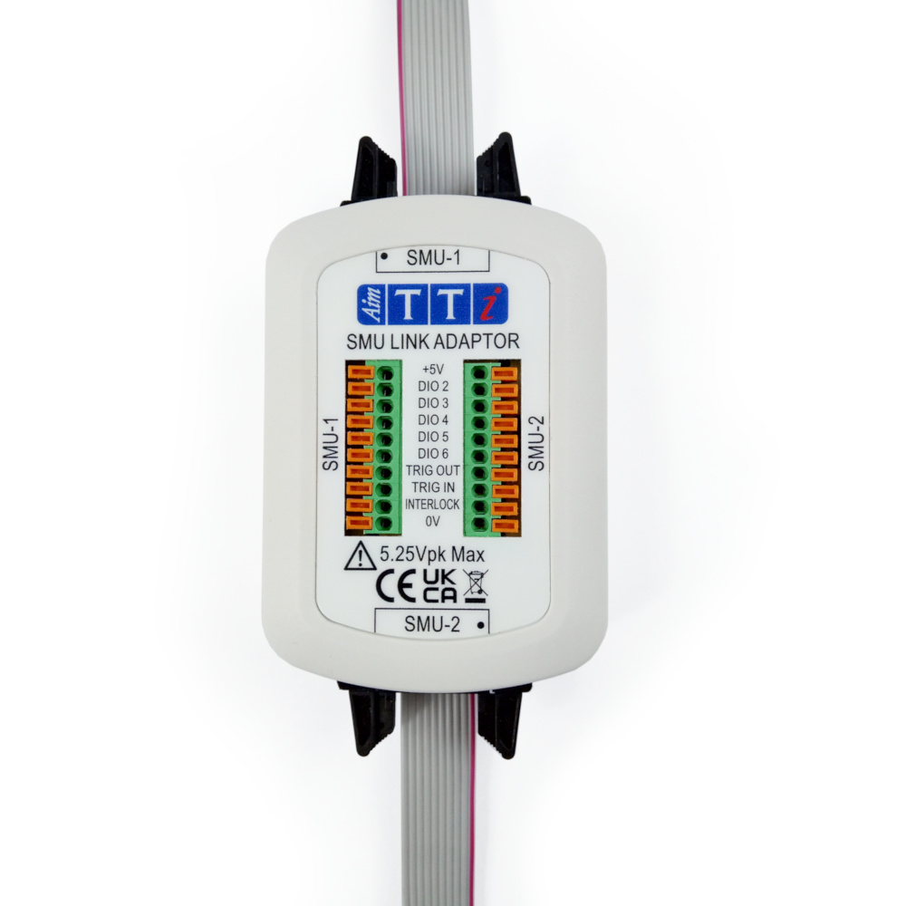
The SMU Link adapter is an optional accessory that can be used to connect two SMU4000 Series units together to perform simultaneously via a handshake triggering system, creating a fully functioning 2 channel SMU for testing three leaded components such as BJTs, FETs or more.
It additionally provides push terminal connectors to access the data lines, triggers and interlocks and for this purpose is useful even if you only have a single SMU4000 series. The SMU-Link adapter also provides access to the +5V and 0V lines for powering external control circuitry. The 5V supply is fused inside the SMU4000 with a 500mA resettable fuse. |
 |
Test Bridge SMU software
 |
Test Bridge SMU SoftwareThe Test Bridge SMU Windows Software provides a graphical interface which allows direct control of the SMU4000 Series hardware, including advanced setups, creation and uploading of lists and sequences, downloading and viewing of tabular or graphical data. Advanced graphing features provide an array of options, some specific to SMU usage such as being able to compare result sets split by step and repeat number for sequenced data. Test Bridge SMU software controls the hardware over the USB or LAN connection (not GPIB) Digital Remote ControlThe SMU4000 Series comes fitted as standard with USB and LAN/LXI interfaces and GPIB is available as an option. The USB 2.0 connection operates as a virtual COM port while the LAN interface conforms to LXI 1.5 Device specifications, 2016. All the interfaces support control by a standard SCPI command set. There is additionally a Digital IO port on the rear panel with 5 user definable signal pins, global trigger in and out and a +5V/500mA DC supply for external low power peripherals. The SMU4201 also has an HV interlock pin for controlling whether the instrument can source voltages above 42V. |
Additional information
| Weight | 4.25 kg |
|---|---|
| Dimensions | 21.35 × 26.9 × 8.65 cm |
| SMU4000 | SMU4001 Source Measure Unit ±20V, SMU4201 Source Measure Unit ±200V |


