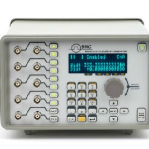

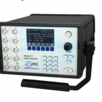
577-4C / 4-Channel Digital Delay Generator
The Model 577 Digital Delay/ Pulse Generator represents the latest in timing capabilities. Eight outputs, each configurable with its own pattern, its own trigger, its own gate, its own delay and width settings, make the 577 our most versatile instrument.

- Description
- Additional information
- OVERVIEW
- SPECIFICATIONS
Description
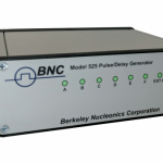
Model 577-4C / 4-Channel Digital Delay Generator (250ps Delay & Width Resolution & 200pS Internal Channel to
Channel Jitter) RS-232, USB Standard
Model 577-4C provides multi-channel 250 ps-resolution timing, delaying, gating, pulsing and synchronizing functions at an attractive price. In addition to the traditional digital delay and pulse generator modes, there are many practical modes of operation and features. For usefulness and value – there is nothing comparable.
Each channel provides both delays and widths – a 4-channel Model 577 provides the same delay and width functionality of competitive 8-channel units. The Model 577 is available in 4 and 8 channel configurations, with optional Ethernet, High Voltage and Dual Input Trigger options.
This Digital Delay/Pulse Generator, representing our finest in precision timing, provides precise delays and widths with 250 pS resolution for times up to 1000 seconds. Low jitter, with both internal clocks (50pS) and using an external trigger (800pS) gives users the timing needed to control many devices. This is particularly useful where several pulses or gate signals need to be delayed and timed with respect to each other or with a common trigger. You may even use one channel as a trigger reference for other channels, locking the timing delays when needed. There is much to learn about the Model 577, which offers much more, including a clock-divider, independent channel triggering, independent amplitudes/channel, delay and width control, and a LabVIEW 8 driver. Give us a call we are happy to discuss your applications.
Additional information
| Weight | 3.62 kg |
|---|---|
| Dimensions | 13.97 × 26.67 × 20.95 cm |
Channel Multiplexing
One of the more unique features of the Berkeley Nucleonics pulse generators is the ability to combine the timing of any or all channels together and output them out of any of the output BNCs. The multiplexing function (MUX) can be set through remote communications via a computer or from the front panel of most units.
Selectable Clock Reference
The Model 577 offers additional inputs and outputs for external clock synchronizing. Specify your input/output reference frequency (10 MHz to 100 MHz). Synchronize with the Mode Lock Oscillator of a laser, or phase lock multiple units with one clock.
Flexible Gating Options

External Trigger Options
Select channels for internal/external triggering, or free-run. Triggered channels have flexible output choices: single pulse, burst at its clock rate, continuous pulse train or a series of on/off pulses (duty cycle). Contact us for custom wave trains or modes.

Individual Rates
Each channel can have individual channel rates (either T0 or any of the other channels…).
Auto-Save
Forgot to save your settings? The Model 577 stores your setup configurations while powering down. Recall is automatic on power-up.
Dual Input Panel Connectors
The Model 577 offers two inputs for triggering or gating. You may specify electrical or optical input signals, and configure any trigger/gate combination. Use Trigger #2 to disable a triggered pulse train.

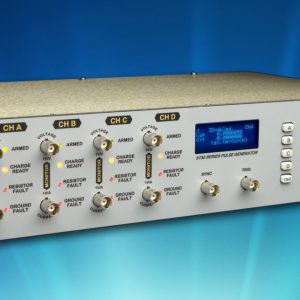
Front Panel High Voltage
Our modular architecture offers expanded functionality on user-selected front panel outputs. We offer a front panel High Voltage option ( adjustable from 35V, 200 mV steps) on 2, 4, 6 or all 8 channels.

Front Panel Optical
Many applications benefit from optical signals. For noisy environments or communications applications, we offer an LED output stage at the front panel. This modular option can be configured for 2, 4, 6 or 8 outputs at 820nm or 1300nm.
Combined Output Types
The outputs are configured in modules and output types are combined in pairs. Thus one may select optical, standard electrical or high voltage electrical in pairs for their instrument. For example, an 8 channel unit may have optical, standard electrical and high voltage outputs all on one instrument. Custom or additional output modules may be added as the need arises. See our handy Order Chart for all option configurations.
Field Programmability
The instrument can now have functions upgraded in the field, such as a special or custom feature upgrade via a fully programmable FPGA.
Custom Output Modes
Custom Modules such as the TZ-50 give users an expanded list of capabilities with the Model 577. One example is our TZ-50 option, which provides customers a TTL signal into 50 ohms expanded.
Negative Delay
Use the handy negative delay feature to reference one channel with respect to another channel in positive or negative time increments. By allowing a channel to reference another channel as its trigger, you can synchronize the channels with respect to each other.
Note that Negative Delay cannot trigger a channel before your initial trigger. It is intended to compliment the channel referencing option.


45V Rise, 50 Ohm, 10nS / Div

45V Rise Hi Z, 10nS / Div
***Due to the power consumption and heat restrictions, a maximum of four AT45 channels can be added on a single unit***
I/O CONFIGURATION
| Model/Output | 577 – 4C: 4 Independent Channels577 – 8C: 8 Independent Channels |
Output Modules:
| Standard AT20 | Dual Channel, TTL/CMOS & Adjustable Output Module |
| Optional L82 | Dual Channel, 820 nm Optical Output Module |
| L130 | Dual Channel, 1300 nm Optical Output Module |
| AT35 | Dual Channel, TTL/35 V High Voltage Output Module |
| AT45 | Dual Channel, 45 V High and Low Impedance Voltage Output Module (limited to 4 channels) |
| TZ50 | Dual Channel, High Current TTL/CMOS (for driving 50 ohm loads) & Adjustable Output Module |
| TZ35 | Dual Channel, High Current TTL/CMOS (for driving 50 ohm loads) & 35 V High Voltage Output Module |
Input Modules:
| Standard IA15 | Dual Channel, 1 Trigger / 1 Gate Input Module * Standard dual channel input module, providing one Trigger input and one Gate input. May be used with the Dual Trigger firmware Option to provide two independent Trigger sources. |
| Optional IL82 | Dual Channel, 820 nm Optical Input Module |
| IL130 | Dual Channel, 1300 nm Optical Input Module |
INTERNAL RATE GENERATOR
| Rate (T0 period) | 0.001 Hz to 20.000 MHz (1000 s – 50 ns) |
| Resolution | 5 ns |
| Accuracy | 5 ns + (0.0001 x period) |
| T0 Period Jitter | < 500 ps RMS |
| Time Base | 200 MHz, low jitter PLL |
| Oscillator | 50 MHz, 50 ppm crystal oscillator |
| System Output Modes | Single, Normal, Burst, Duty Cycle, External Gate/Trigger |
| Burst Mode | 1 to 10,000,000 pulses |
| Duty Cycle Mode | 1 to 10,000,000 pulses ON and/or OFF |
| Pulse Control Modes | Internally triggered, externally triggered or external gate. |
CHANNEL TIMING GENERATOR
| Pulse Width Range | 10 ns -1000 s |
| Width Accuracy | 1 ns + [0.0001 x (width + delay)] |
| Width Resolution | 50 ps |
| Pulse Delay Range | 0 – 1000s |
| Delay Accuracy | 1 ns + (0.0001 x delay) |
| Delay Resolution | 250 ps |
| Jitter (channel to channel) | < 250ps RMS |
| Output Multiplexor | Any/all channels may be OR’d to any/all outputs. |
| Time Base | Same as internal rate generator |
| Channel Output Modes | Single, Normal, Burst, Duty Cycle |
| Burst Mode | 1 to 10,000,000 pulses |
| Duty Cycle Mode | 1 to 10,000,000 pulses ON and/or OFF |
| Wait Counts | 1 to 10,000,000 pulses |
| Channel Control Modes | Internally triggered or external gated. Each channel may be independently set to either mode. |
STANDARD FEATURES
| Communications: | |
|---|---|
| USB | USB 1.0 Standard |
| RS-232 | DB-9 Connector using RS-232 Communications Standard |
| External Clock In | 10 MHz – 100 MHz user selectable in discrete values |
| External Clock Out | To or Ref out (10 to 100 MHz) user selectable in discrete values |
SYSTEM OPTIONS
| DT-15 | Dual Trigger Logic – provides atditional trigger via gate input |
| COM | Extended Communications – Atds Ethernet & GPIB |
| SRM | Single Rack Mount |
| DRM | Dual Rack Mount |
GENERAL
| Storage | 16 storage bins |
| Dimensions | 10.5” x 8.25” x 5.5” |
| Weight | 8 lbs |
| Power | 100 – 240 VAC 50/60 Hz <3 A |
| Fuse | (Qty 2) 3.15 A, 250 V Time-lag |
| Temperature | |
|---|---|
| Operation | 0 – 40°C (32 – 104°F) |
| Transportation & Storage | -40 – 70°C (-40 – 158°F) |
MODULE SPECIFICATIONS
| TTL/Adjustable Dual Channel Output Module | (Standard) |
| Output Impedance | 50 ohm |
| TTL/CMOS Mode: | |
| Output Level | 4.0 V typ into 1 kohm |
| Rise Time | 2.8 ns typ (10% – 90%) |
| Slew Rate | > 0.5 V/ns |
| Jitter | 50 ps RMS channel to channel |
| Adjustable Mode | |
| Output Level | 2 V to 20 VDC into 1 kohm |
| 1 V to 10 VDC into 50 ohm | |
| Output Resolution | 10 mV |
| Current | 200 mA typical, 400 mA (short pulses) |
| Rise Time | 15 ns typ @ 20V (high imp) |
| 25 ns typ @ 10V (50 ohms) | |
| (10% – 90%) | |
| Slew Rate | > 0.1V/ns |
| Overshoot | < 1 V + 10% of pulse amplitude |
| Trigger/Gate Dual Input Module | (Standard) |
| Trigger Input: | |
| Function | Generate individual pulses, start a burst or continuous stream |
| Rate | DC to 1/ (200 ns + longest active pulse). Maximum of 5 MHz |
| Slope | Rising or Falling |
| Threshold | 200 mV to 15 VDC |
| Maximum Input | 60 V Peak |
| Resolution | 10 mV |
| Trigger Accuracy | ±3% of Threshold Voltage |
| Impedance | 5.3 kohm + 40pF |
| Rate | DC to 20 MHz |
| Trigger Jitter | < 20 ns RMS |
| Insertion Delay | < 110 ns |
| Minimum Pulse Width | 20 ns |
| Pulse Inhibit Delay | < 150 ns RMS |
| Output Inhibit Delay | < 100 ns RMS |
| Gate Input: | |
| Mode | Pulse inhibit or output inhibit |
| Polarity | Active high/active low |
Optical Outputs
| Wavelength | 820 nm or 1300 nm |
| Maximum Signal Rate | 5 MBd |
| Maximum Link Dist. | 1.5 km |
| Connector Type | ST |
Optical Inputs
| Wavelength | 820nm or 1300nm |
| Maximum Signal Rate | 5 MBd |
| Maximum Link Dist. | 1.5 km |
| Connector Type | ST |
| Insertion Delay | < 300 ns |
| Jitter | < 1.4 ns RMS |
AT35 SPECIFICATIONS
| Through a 50? load at 200 Hz | |
| Output | 5 V – 35 V |
| Setpoint Resolution | 10 mV |
| Rise Time | < 30 ns |
| Accuracy | 500 mV |
| Max. Frequency (Internal & External) | 4 kHz |
TZ50 SPECIFICATIONS
| TTL/CMOS Mode | |
| Output Level | 4.0 V typ into 50 Ohms |
| Rise Time | 2.8 ns |
| Slew Rate | 0.5 V/ns |
| Jitter – Channel to Channel | 50 ps RMS |
| Adjustable Mode | |
| Output Resolution | 10 mV |
| Current | 100 mA typ, 400 mA max (short pulses) |
| Slew Rate | 0.1 V/ns |
AT45 SPECIFICATIONS
| Amplitude | 4 V – 45 V |
| Resolution | 20 mV |
| Accuracy | +/-1.5% |
| Rise Time | < 2ns Typical 10%-90% (Low Z)
< 9ns Typical 10%-90% (High Z) |
| Fall Time | < 9ns Typical 90%-10% (Low Z)
< 9ns Typical 90%-10% (High Z) |
| Frequency (Internal & External) | DC – 100 kHz |
| Overshoot | |
| Polarity – High Z (>10k) | Active High or Active Low |
| Polarity – Low Z (50 Ohms) | Active High Only |
| Pulse Width – High Z (>10k) | 10 ns to DC |
| Pulse Width – Low Z (50 Ohms) | 10 ns to 10 s |
| Current (maximum) | 35 mA (High Z @10 ms width) 900 mA (Low Z @ 10 ms width) |
| Part Number | Description |
| P/N6923 | Model 577 19″ Rack Mount |
| P/N6978 | Model 577 19″ Dual Rack Mount |